Introduction

If your Logitech G X56 HOTAS Joystick (model 945-000058) isn't responding to input from the Flying Pinky switch, use this guide to replace the defective switch.

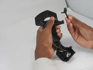
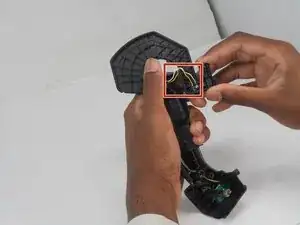
The Flying Pinky is a switch near the joystick's base and is commonly used for control modifiers or toggling secondary functions during flight simulation. A defective switch can lead to missed commands, inconsistent activation, or no response.

Before using this guide, inspect the switch for physical damage or signs of debris that may be interfering. Be sure to check the joystick on a different USB port or computer to rule out software conflicts.

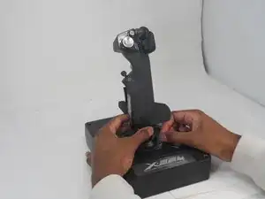
Before beginning, disconnect the joystick from your computer and any power source.

  1. kk24GUtyyGRpVUDg
    kk24GUtyyGRpVUDg
    dhMNKSBLfapTv6gx
    • Turn the locking bezel counterclockwise, then remove the joystick from the joystick base.

  2. VVSqSavQFyZLHXhq
    VVSqSavQFyZLHXhq
    j4IT5oIlyHF3iPi3
    DDgaM3LGqxMprcNW
    • Remove the five 11.7 mm-long Phillips #0 screws that secure the case.

  3. m3vY3ZH5DS35kZom
    m3vY3ZH5DS35kZom
    FgWpmrLWWgHLtXG6
    • Pull the joystick casing apart to reveal the internal components.

    • The casing will need a little force to split open.

    • Take care not to damage or strain the connected cable.

  4. ZIPy1jcMvRYaQFiA
    ZIPy1jcMvRYaQFiA
    5bqY2vEValSwftvw
    • Grip and pull the white connector directly out of its socket.

    • The connector is fragile. If removed forcefully, it may affect the PCB performance.

  5. KQmvvqKppKoQBG3B
    KQmvvqKppKoQBG3B
    yIVtE2gmYScrUnFk
    • Refer to the left or right side for replacement guides of other parts (left, then right side in order).

  6. axySTHGeOON3quH4
    axySTHGeOON3quH4
    NSU5vEX1OPgLradO
    GmK4PpfIKkTNweTp
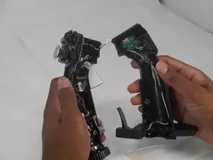
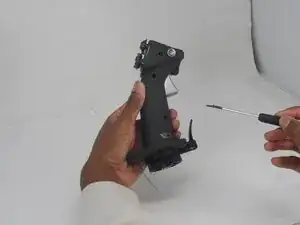
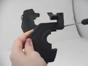
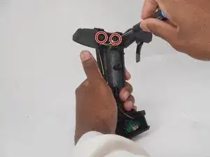
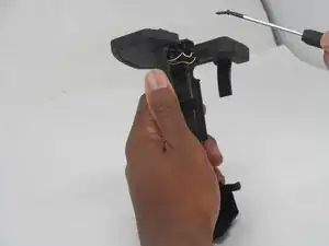
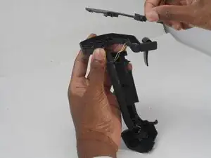
    • Remove the following screws on the underside of the right joystick half:

    • Three Phillips #000 5.7 mm screws

    • Two Phillips #00 6.9 mm screws

  7. 2SZ5PUNOAfZDXOM2
    2SZ5PUNOAfZDXOM2
    l3MqGjPfGfCJSHLB
    • Remove the two Phillips #0 11.7 mm screws.

  8. IkGMBQZtnFxrZDif
    IkGMBQZtnFxrZDif
    5AFLWHP3lwvp6iNy
    • Separate the base plate connected to the joystick casing.

    • Take care not to strain the connected cables.

  9. RrbZTc3Dk1bdYZvy
    • Remove the top panel of the base plate.

  10. XtKCYVDcM1KfQWPj
    XtKCYVDcM1KfQWPj
    uPRn4oCGVnp3HLUN
    • Use your fingers to remove and flying pinky switch.

    • If not done carefully, the yellow and white wiring connecting to the PCB board and the spring attached to the flying pinky will fall out.

Conclusion

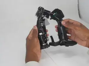
To reassemble your device, follow the above steps in reverse order.
Repair didn’t go as planned? Try some basic troubleshooting or ask our Answers community for help.

Hannah Henderson

Member since: 19/02/25

555 Reputation

0 comments